- Confirm that the problem is failed solution delivery rather than failed water recovery, then classify it as no flow, low flow or uneven flow.
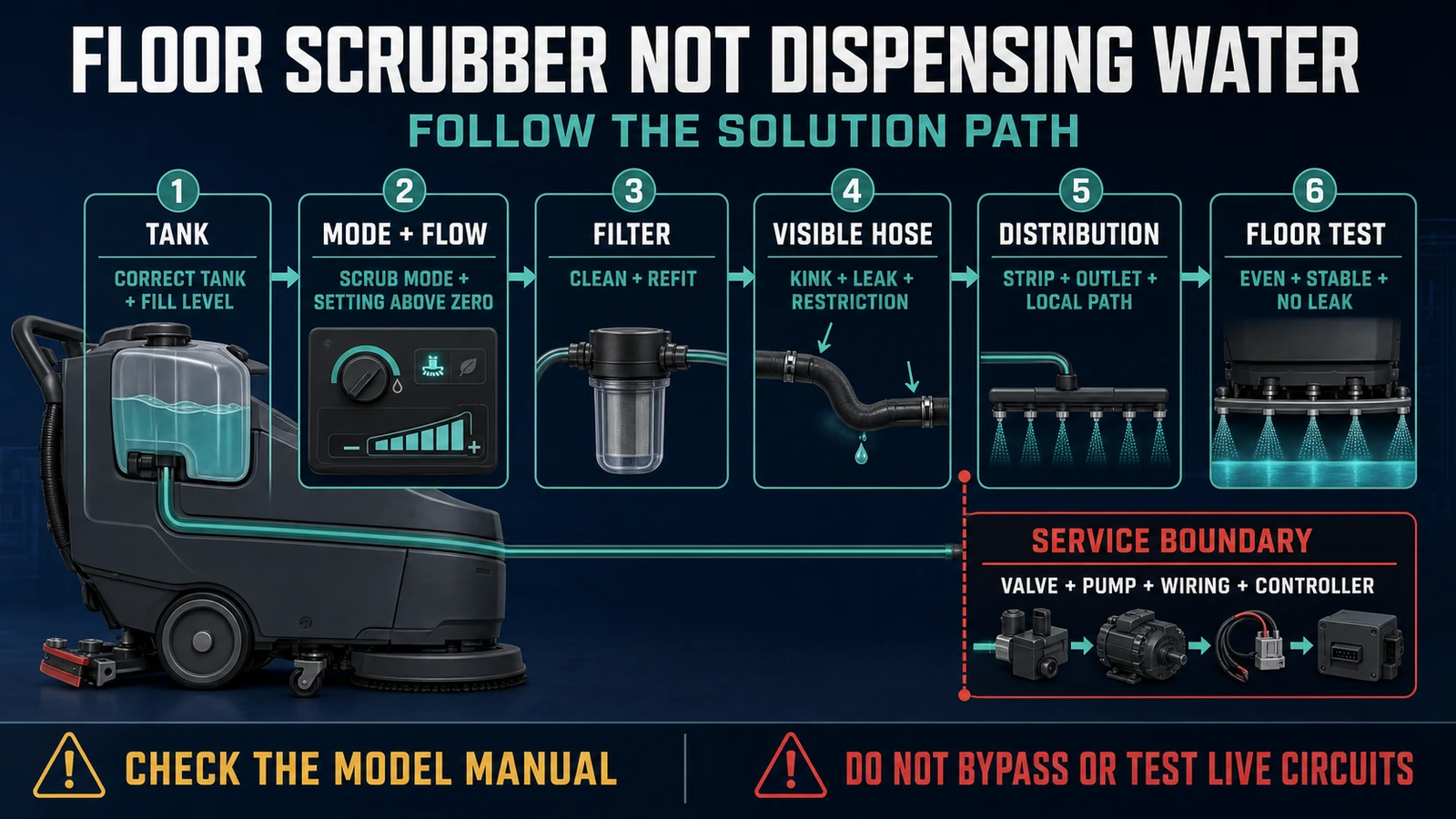
- Check the solution path in order: correct tank and fill level, operating mode and flow setting, operator-accessible filter, visible hose and distribution parts.
- Stop at the service boundary for an internal valve, pump, wiring or controller fault, recurring error, internal leak or solution that continues to flow after shutdown.
In this article 14 sections
If a floor scrubber is not dispensing water, do not start by replacing the pump. Confirm that the correct solution tank is filled, the machine is in a mode that permits solution flow, and the flow setting is above zero. Then inspect the operator-accessible filter, visible hose path and water-distribution parts in the order specified by the exact model manual.
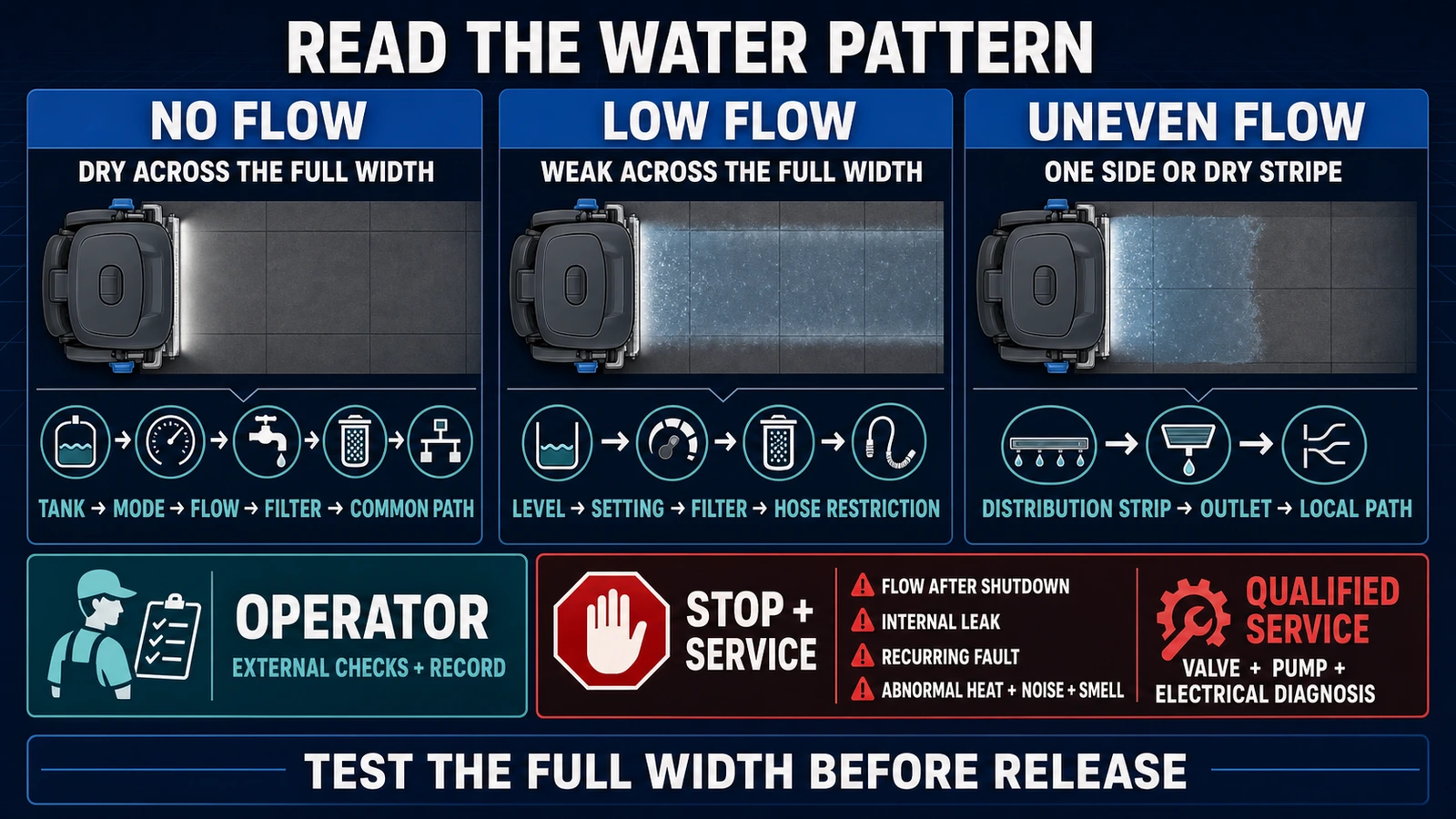
Classify the symptom before taking anything apart: no flow anywhere, low flow across the cleaning width, or uneven flow at one side or section. Stop and contact qualified service if the fault involves an internal valve, pump, wiring or controller; if a fault code returns; if the machine leaks internally; or if solution continues to flow after shutdown.
Floor Scrubber Solution-Flow Problems at a Glance
| Symptom | Likely area to investigate | First safe action |
|---|---|---|
| No solution reaches the floor | Empty or incorrect tank, disabled flow, operating-mode condition, clogged filter, restricted supply path or internal fault | Confirm tank, mode and flow setting with the exact manual |
| Flow is weak across the full width | Low setting, low level, dirty filter, restricted hose or dirty distribution system | Compare the current setting and external path with a known normal condition |
| One side or strip stays dry | Local distribution strip, outlet, nozzle or branch restriction | Clean only the operator-accessible part named in the manual |
| Flow appears only while the machine moves | Model-specific speed-linked dosing or scrub-mode logic | Verify that this behavior is normal for the model before diagnosing a fault |
| Solution leaks while parked or switched off | Valve contamination, damaged valve, internal leak or control fault | Isolate the machine, protect the area and call service |
| Flow returns after reset, then fails again | Intermittent pump, connector, wiring, controller or protection fault | Record the code and condition; stop repeated resets |
| Water reaches the floor but remains behind | Recovery tank, squeegee, hose, seal, float or vacuum problem | Use the separate water-recovery troubleshooting guide |
First Separate Dispensing Failure from Recovery Failure
A scrubber dryer has two liquid paths. The solution system delivers clean water or cleaning solution to the brush or pad area. The recovery system collects dirty water through the squeegee and vacuum path.
Run a controlled observation on a compatible floor:
- If the path remains dry and unwashed, investigate solution delivery.
- If solution reaches the floor but a wet trail remains, investigate recovery.
- If the floor is damp but cleaning is poor, check flow, chemistry, brush or pad selection, speed and soil—not the vacuum alone.
This distinction prevents a common parts mistake. A machine can leave a dry path because its flow is off, and it can leave a wet path even though its solution system is working correctly. World Clean Biz's floor scrubber water-pickup guide owns the recovery-tank, squeegee, vacuum-hose and vacuum-system fault tree.
Stop and Isolate the Machine Before Inspection
Move the machine to an approved inspection area and follow the shutdown procedure for its exact model and configuration. Protect any wet or chemically affected floor.
At minimum:
- release the operating controls and stop on a suitable level surface;
- switch off and remove the key or access device where the manual requires it;
- disconnect charging power before any permitted maintenance;
- keep hands away from brushes, pads, linkages and drive components;
- do not bypass a valve, interlock, sensor, fuse or safety device;
- do not open electrical panels or test a live circuit;
- use the required gloves, eye protection and chemical-handling procedure.
The Tennant T500 operator manual uses a model-specific isolation sequence: stop on a level surface, turn off the machine, remove the key and set the parking brake if equipped. The Kärcher B 50 W manual requires its program switch at zero, removal of the Intelligent Key and disconnection of the charger plug before work. These are examples, not a universal lockout procedure.
How the Solution-Delivery Chain Works
A conventional floor scrubber moves liquid through a series of dependent stages:
- The correct tank holds water or a prepared cleaning solution.
- The machine's operating logic permits flow in the selected cleaning mode.
- A manual or electronic setting controls the requested amount.
- A filter or screen protects the downstream path.
- A hose carries liquid toward the cleaning head.
- A valve, solenoid, pump or gravity-fed arrangement controls movement.
- A distribution strip, manifold or outlets spread liquid near the brush or pad.
The order and components vary. Some machines meter solution according to travel speed. Some use a manual valve. Some add detergent downstream from a clean-water tank. A proprietary water-treatment system may have different filling and chemistry rules from conventional scrubbing.
Use this chain as a diagnostic map, then confirm every access point in the model manual. Do not assume the machine has a vented cap, a removable nozzle or an operator-serviceable pump.
Check the Correct Tank, Fill Level and Chemistry
Start with the simple question: is the intended supply available to the system?
- Confirm the operator filled the solution or fresh-water tank—not the recovery tank or a separate detergent container.
- Verify the level using the machine's specified indicator or visual method.
- Check that a drain hose, cap or tank fitting disturbed during cleaning is returned to its operating position.
- Confirm that any model-specific shutoff or solution valve identified for operator use is open.
- Verify that the liquid and mixing method match the machine, floor and cleaning program.
The T500 manual lists an empty solution tank as the first cause of little or no flow. Its conventional mode calls for commercially approved cleaning detergent mixed according to the product instructions, while its optional ec-H2O configuration has different requirements. This is why a refill made with the wrong system assumption can create a new fault instead of correcting the original one.
The Nilfisk SC500 instructions specify low-foam, non-flammable detergent intended for automatic scrubbers and require the user to follow the chemical label and protective-equipment instructions. Do not use flammable material, an unapproved descaler or a high-foaming consumer detergent as a troubleshooting shortcut.
Chemistry can contribute to residue, deposits or a blocked path, but it does not justify pouring a stronger chemical into the tank. Follow the approved tank-cleaning or descaling procedure, if one exists, for the exact machine.
Verify the Operating Mode and Flow Setting
A full tank does not prove that the machine is requesting flow.
Before cleaning a component, verify:
- the correct scrub or cleaning program is selected;
- the flow setting is not at zero or disabled by a stored supervisor setting;
- the brush deck, pad driver or other required assembly is in the operating position;
- the machine is being tested under the movement or trigger condition described by the manual;
- a water-only, detergent, eco or specialty mode has not changed the expected output.
The SC500 manual illustrates why this step is model-specific. Flow level zero closes solution flow, while its first three flow levels adjust output according to machine speed. Its One-Touch control, EcoFlex option and REV mode also change how scrubbing, water and detergent behave. Watching a stationary machine and seeing no water therefore may not prove a fault.
The T500 troubleshooting table includes a low flow-rate setting alongside an empty tank, a clogged filter and a blocked supply line. The B 50 W manual similarly tells the operator to check the fresh-water level and increase the water quantity before moving further down the path.
Record the starting setting before changing it. If a supervisor has locked a program or the model uses configured zones, do not override the control to create a temporary workaround.
Clean the Operator-Accessible Solution Filter
A dirty filter can reduce flow across the full cleaning width or stop it entirely. Tennant, Nilfisk and Kärcher manuals all identify the solution or fresh-water filter as a routine check for insufficient flow.
Use only the exact manual procedure:
- Isolate the machine and drain liquid if required.
- Locate the correct clean-water or solution filter; do not confuse it with a recovery-air filter.
- Remove it only if the operator instructions permit removal.
- Rinse or clean it by the approved method.
- Inspect the seal, housing and installation direction.
- Refit it fully before adding liquid and testing.
Do not run the machine without the filter to “prove” flow. That can move debris into a valve, pump or distribution passage. Do not substitute a mesh that merely looks similar; filtration area, seal geometry and chemical compatibility matter.
If the filter repeatedly blocks, record what is found. Tank debris, chemical residue, poor rinsing practice, contaminated refill containers or damaged tank components may be feeding the restriction.
Inspect Visible Hoses and Distribution Parts
After the tank, controls and filter, follow the visible supply route toward the cleaning head.
Look for:
- a hose that is kinked, pinched or trapped after tank or deck movement;
- a loose or partially seated connection;
- external abrasion, cracking, swelling or leakage;
- a visible restriction at an operator-accessible fitting;
- debris or buildup on a removable distribution strip, outlet or nozzle;
- a component installed backwards or not latched after maintenance.
Kärcher's B 50 W troubleshooting table directs the user to clean the fresh-water filter, clean the distribution strip on the applicable roller head and check hoses for clogging. The Tennant 5680 manual likewise maps low or no flow to the tank, flow control, supply line, filter and solenoid.
Stop at the method boundary. Do not push wire, drill bits or improvised tools into a nozzle or hose. Do not apply compressed air, high-pressure water or concentrated chemical unless the manufacturer explicitly authorizes it for that component. An aggressive clearing method can enlarge an outlet, puncture a hose, move debris deeper into the system or send liquid toward electrical parts.
Diagnose No Flow, Low Flow and Uneven Flow Separately
The water pattern narrows the fault without identifying a failed part by itself.
No flow anywhere
Confirm the tank, operating mode, flow setting and filter first. Then inspect the common visible supply path. If these checks pass and the machine remains dry, the fault may be beyond the operator boundary: an internal valve, solenoid, pump, connector, wiring fault or controller problem.
Low flow across the full width
Compare the current result with a known normal setting on the same machine. Check liquid level, flow selection, filter condition and a restriction in the common hose. A low-flow complaint can also arise when speed-linked dosing is observed under a different travel condition.
Do not keep raising the setting to hide a restriction. That can produce unstable output, excess water after the blockage shifts, longer drying time and an inconsistent cleaning result.
Uneven or one-sided flow
When one side stays dry while another receives solution, begin at the downstream distribution part rather than the tank. Inspect the operator-accessible strip, outlets, local hose branch and installation. A local dry stripe is stronger evidence of an end-of-line distribution problem than of a completely failed pump.
Flow after shutdown
Solution that continues to drip or run after the machine is switched off is a stop-use condition. The Nilfisk SC650 service manual associates leakage onto the brushes or floor while the machine is off with contamination, scale or failure at the solenoid valve. That is service-level evidence, not an instruction for the operator to remove the valve.
Stop at the Valve, Pump and Electrical Service Boundary
An internal component should be diagnosed by function and evidence, not guessed from the symptom. A valve can stick, a pump can fail, a connector can loosen, wiring can open intermittently, or a controller can stop commanding flow. Different faults can produce the same dry floor.
End operator troubleshooting when:
- the manual's external checks are complete and flow has not returned;
- a pump, solenoid, internal valve, wiring, connector or control board is suspected;
- the machine displays a recurring fault code or repeatedly trips a protective device;
- solution reaches an electrical or battery area;
- an internal hose or fitting leaks;
- solution continues to flow after shutdown;
- there is abnormal heat, noise, smell, smoke or damaged visible wiring;
- a safety device, interlock or access cover is missing, modified or ineffective;
- the correct procedure or responsibility is uncertain.
Tennant's T500 fault guidance sends pump, pump-control and control-panel faults to service. Nilfisk's SC500 manual states that operators must not perform procedures reserved for qualified technicians. Kärcher's B 50 W manual prohibits bypassing or disabling safety devices and directs unresolved table faults to Customer Service.
Do not repeatedly reset the machine without recording the code and operating condition. An intermittent fault that clears briefly can still leave an area unwashed, create a leak or fail during the next shift.
Test Before Returning the Machine to Service
An external correction needs an operating test. Use an approved test lane on a compatible floor, with the correct brush or pad and authorized chemistry.
- Record the model, configuration, meter hours, original symptom and starting settings.
- Fill the correct tank to an appropriate test level.
- Reinstall all filters, caps, hoses, covers and guards.
- Select the normal site-approved cleaning mode.
- Run a defined straight lane under the operating conditions required by the manual.
- Observe the full cleaning width for no-flow, low-flow or dry-stripe behavior.
- Check the machine and parked area for leakage.
- Confirm that water recovery is also functioning before returning to production.
- Record the corrective action, result and person releasing the machine.
A pass means the solution pattern is stable and appropriate for the task, the machine shows no abnormal warning or leak, and the recovery system leaves the test area safe under the site's acceptance criteria. If the result changes between runs, keep the machine isolated.
Prevent the Same Flow Restriction from Returning
Recurring solution-flow faults should become a maintenance and process review. The site should know:
- who rinses the solution tank and cleans the filter;
- which refill containers and water source are approved;
- which detergent, dilution method and dosing system apply to each configuration;
- how hoses and distribution parts are checked after tank or deck access;
- which filter, seal, hose and distribution-part numbers belong to the asset;
- how meter hours, settings, fault codes and corrective actions are recorded;
- who owns service escalation and the backup-machine decision.
Use the floor scrubber preventive maintenance checklist to place these tasks into pre-shift, daily, weekly and manufacturer-scheduled work. Keep the fault page and the maintenance page separate: this guide diagnoses an active dispensing problem; the checklist controls recurring care.
The procurement process should also test how easily an operator can see the liquid level, reach the routine filter, inspect the visible hose path and clean the distribution part. World Clean Biz's commercial floor scrubber buying guide explains how maintainability, service support and a measured site trial belong in the purchase decision.
FAQ
Why is no water coming out of my floor scrubber?
Common operator-level causes include an empty solution tank, a flow setting at zero or too low, a cleaning mode that is not requesting flow, a dirty solution filter, a restricted visible hose or a dirty distribution part. If these checks pass, a valve, pump, wiring or controller fault may require qualified service.
How do I know whether the solution pump has failed?
You cannot confirm a failed pump from a dry floor alone. First eliminate the tank, operating mode, flow setting, filter and visible supply path. Pump diagnosis can require internal access and electrical testing, so follow the service procedure for the exact machine.
Why does my floor scrubber dispense water only while moving?
Some scrubbers link solution output to travel speed or activate flow only under specific scrub-mode conditions. Nilfisk's SC500, for example, adjusts its first three flow levels according to machine speed. Check the exact manual before treating stationary no-flow as a fault.
Why is the water flow weak across the whole scrub deck?
A low setting, low tank level, dirty filter or restriction in the common supply hose can reduce flow across the full width. Compare the result under a defined setting and travel condition rather than increasing the control repeatedly.
Why is only one side of the floor scrubber dry?
A local restriction or incorrect installation at the distribution strip, outlet, nozzle or branch hose is more likely than an empty tank. Clean or refit only the parts assigned to the operator by the manual.
Can I run the floor scrubber without the solution filter?
No. Removing the filter can send debris into the valve, pump or downstream distribution path. Clean or replace it with the correct part according to the manual.
Can I use compressed air or wire to clear a blocked solution line?
Only if the manufacturer explicitly specifies that method for the exact component. Improvised tools or pressure can damage hoses and outlets, move debris deeper or expose electrical parts to liquid.
When should I call a floor scrubber technician?
Call qualified service when external manual-approved checks do not restore flow, or when the fault involves an internal valve, pump, wiring, connector or controller; a recurring error; internal leakage; abnormal heat, noise or smell; or solution that continues to flow after shutdown.
Final Answer
When a floor scrubber is not dispensing water, diagnose the supply path in order: correct tank and fill level, operating mode and flow setting, operator-accessible filter, visible hose and distribution parts. Separate no flow, low flow and uneven flow before replacing anything.
Keep valves, pumps, wiring and controllers inside the qualified-service boundary. After any correction, prove stable, even solution delivery on a controlled lane, check for leaks and confirm water recovery before documenting the machine's return to service.