- A no-loop-signal message does not prove that the buried wire is completely broken; station power, connectors, partial damage, incorrect topology and station hardware must also be separated.
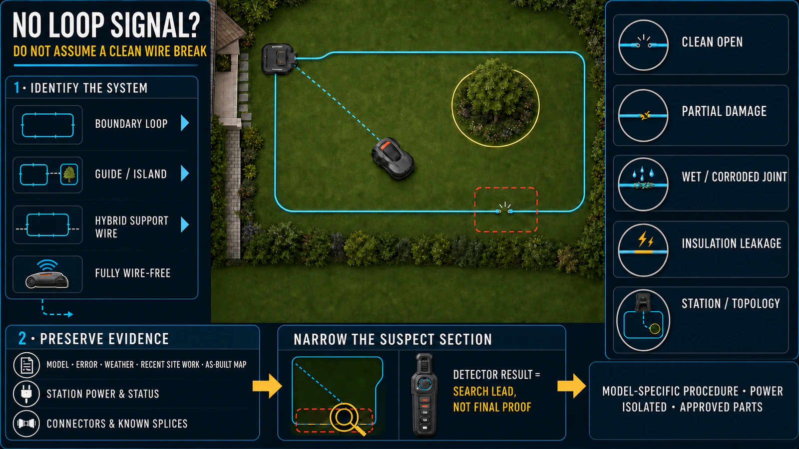
- Identify whether the site uses a boundary loop, guide wires, a hybrid support wire or a fully wire-free system before applying any test procedure.
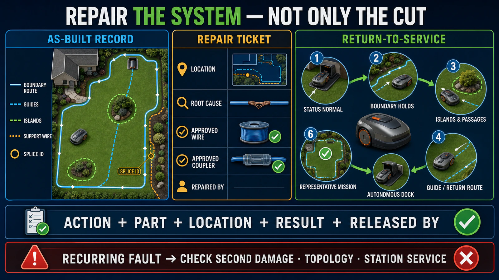
- Use the exact model manual and approved wire and couplers, then verify boundaries, islands, passages, return-to-dock behavior and a complete mission before release.
In this article 16 sections
A robot mower boundary wire break can cause a no-loop-signal error, but the message does not prove that the buried cable has a clean break. First identify the installation architecture and preserve the evidence. Then check station power, accessible connectors and known splices before narrowing the suspect section. Partial conductor damage, wet or corroded joints, insulation leakage, incorrect reconnection and station electronics can produce similar or intermittent symptoms.
Repair only with the wire and weatherproof couplers approved for the exact system. Do not apply another brand’s LED chart, resistance threshold or terminal-switching procedure. A repair is complete only after the mower respects the full boundary, islands and passages, follows any guide or return route, docks correctly and completes a representative mission without the fault returning.
How to Find a Robot Mower Boundary Wire Break: Quick Steps
- Record the exact mower error, station light and recent landscaping, edging or weather event before moving any connector.
- Confirm that the installation actually uses a physical boundary, guide or hybrid support wire.
- Follow the model manual to isolate the station safely, then check station power and photograph the original terminal positions.
- Inspect accessible connectors and known splices before tracing buried cable.
- Narrow the suspect section using recent-work evidence, the manufacturer’s sectional method or a compatible wire-break detector.
- Repair the complete damaged section with approved wire and weatherproof couplers, then verify the whole boundary, return path and docking cycle.
These are diagnostic stages, not universal wiring instructions. Terminal layouts, indicator meanings, resistance limits and isolation procedures vary by model and market.
No-Loop-Signal Faults at a Glance
| Observation | Possible fault area | First safe action |
|---|---|---|
| Station has no power or status | Site supply, power supply, low-voltage cable, connector or station | Preserve the state and troubleshoot the power path before the loop |
| Error appeared after edging, aeration, trenching or landscaping | Cut, crushed or stretched wire near recent work | Mark the work area and inspect the as-built route |
| Error appeared after rain or irrigation | Wet joint, damaged insulation, corrosion or water ingress | Record weather timing; do not assume a clean open circuit |
| Complete no-loop condition | Open connector, clean break, disconnected terminal or station fault | Check accessible connections and known splices first |
| Intermittent fault or high-resistance condition | Partial conductor damage, weak joint, corrosion or movement | Preserve timing and environmental evidence before disturbing joints |
| Mower turns or reverses erratically near one edge | Insulation damage, signal leakage, wire geometry or local installation issue | Mark the exact location and compare it with the route map |
| One boundary section tests differently from another | Local cable, splice or topology problem | Narrow the section using the manufacturer’s method |
| Wire checks appear normal but fault remains | Wrong reconnection, guide-wire issue, pairing/calibration or station electronics | Restore original topology and escalate with records |
| Hybrid RTK system fails only in a support-wire area | Physical support wire, connection or local map/configuration | Identify the hybrid architecture before testing |
First Identify the Boundary Architecture
Do not begin by cutting or swapping wires. Record what the site actually uses:
- a continuous physical boundary loop;
- one or more guide wires connected to the boundary system;
- physical island loops around excluded areas;
- a hybrid installation using virtual boundaries plus a physical support wire;
- a fully wire-free RTK, LiDAR or vision system.
A fully wire-free mower does not have a perimeter-wire break to find. Its equivalent symptom may belong to map, positioning, reference-station, network, sensor or docking systems. World Clean Biz’s wire-free robot mower guide explains those architectures.
Hybrid systems require particular care. Husqvarna’s current EPOS Support by Wire guidance describes a physical support wire used in areas with weak satellite signal while the larger work area remains virtual. A technician who records only “RTK mower” may miss the physical circuit that actually failed.
The intake record should therefore include mower and station model, serial number, market version, installed navigation mode, boundary and guide configuration, known splice locations, last successful operation and any recent site work.
A No-Loop Message Is Not Proof of a Broken Wire
For current Automower products, Husqvarna says a `No loop signal` message indicates a communication problem between the mower and boundary wire; on certain older products it may also involve the guide wire. Its support material lists connection faults, damaged wire and charging-station hardware among possible causes.
That distinction matters across the category. “No signal” is an observed system state, not a component verdict. The failure can sit in:
- station power and external connections;
- the boundary or guide terminals;
- a known splice or branch point;
- a clean open circuit;
- a partially broken conductor or high-resistance joint;
- damaged insulation and signal leakage;
- an incorrect island, guide or terminal topology;
- the station transmitter or control electronics.
The exact LED color and error code are model-specific. Record them, but interpret them only with the manual for the complete model and region. A familiar blue, green or red light from one station is not a category standard.
Preserve Evidence Before Moving Connectors
Loop faults often become harder to diagnose after several joints have been opened, wires exchanged or settings reset. Capture the original state first:
- exact error message, code, station light and App status;
- whether the fault is permanent or intermittent;
- time, weather, irrigation and soil condition when it appears;
- recent edging, scarifying, aeration, fencing, drainage, planting or utility work;
- locations where the mower turns, stops or crosses incorrectly;
- photos of every accessible station connection and known splice;
- the installation drawing, wire route, island direction and guide-wire connections;
- prior repairs, coupler identifiers and dates;
- whether another machine, station or firmware change preceded the fault.
This evidence is commercially useful. It helps a dealer decide whether the visit is likely to be ordinary wire repair, site restoration, warranty assessment or station service. It also reduces the risk that the service team creates a second topology error while looking for the first fault.
Work Safely Around Outdoor Power and Buried Cable
Boundary-wire systems normally use a low-voltage signal, but the charging station is still connected to an outdoor power path. Water, damaged power equipment and improvised testing can create risks outside the loop wire itself.
- Stop the mower and isolate the station exactly as its manual requires before opening accessible loop connections or repairing cable.
- Do not work on wet, flooded, burned or visibly damaged station equipment.
- Do not open the power supply, charging station or mower electronics.
- Do not probe energized outdoor terminals or inject an improvised signal.
- Use utility-location and site-permit procedures where excavation could encounter other services.
- Keep the mower out of unattended operation until boundary protection is verified.
If the site supply, protective device, power cable, station electronics or water ingress is involved, use qualified or authorized service. This article explains diagnostic structure; it does not replace the model manual or site electrical rules.
Check Station Power, Connectors and Known Splices First
Before searching hundreds of metres of buried cable, follow the shortest and most observable path.
1. Confirm the station’s model-defined status
If the station has no power or its external supply is damaged, the loop may not be energized even when the wire is intact. Separate a power-path problem from a loop-path problem using only the checks assigned to the operator or installer by the exact manual. The related robot mower charging guide owns the broader station-power and charging diagnosis.
2. Inspect accessible boundary and guide connections
Look for a loose, incompletely inserted, corroded, crushed or incorrectly assigned connector. Photograph the topology before removing anything. Confirm the terminal names from the station manual rather than from memory.
3. Inspect known splices and prior repair points
Husqvarna’s current wire-break guide begins with station connectors and known splices and recommends using the installation map. Joints are efficient checkpoints because they combine electrical and environmental risk, but finding one poor joint does not prove that it is the only fault.
4. Compare the failure with recent site events
A fault immediately after edging, a new fence, drainage work or aeration provides a high-value search area. After heavy rain, a joint or damaged insulation may behave differently without becoming a complete clean break.
Separate Four Cable-Fault Patterns
“Broken wire” is too broad for efficient service.
| Fault pattern | Typical behavior | Diagnostic implication |
|---|---|---|
| Clean open circuit | Loop signal is absent and usually remains absent | Visual route history, sectional narrowing or a suitable detector may locate it |
| Partial conductor damage | Fault may appear with movement, moisture or temperature | A detector optimized for a clean break may miss it |
| Wet/corroded high-resistance joint | Intermittent or degraded signal, often linked to weather | Inspect joint history and replace the complete damaged section as specified |
| Insulation damage/signal leakage | Mower may behave erratically near a location before total failure | Mark local behavior and inspect cable condition and geometry |
Husqvarna notes that a wire-break detector can be useful for a clean break but may be less effective for a partial break. Worx’s model-specific support for erratic reversing near a boundary also shows why a cable can create behavior problems before producing a simple all-or-nothing error.
Locate the Fault Without Turning One Brand’s Procedure into a Universal Rule
There are three general routes to localization.
Visual and event-led search
Walk the mapped route and prioritize exposed cable, old joints, tight bends, transitions, gate openings and recent work. This is fastest when the site history is reliable.
Manufacturer-defined sectional narrowing
The principle is to create known test sections and repeatedly reduce the suspect length. Husqvarna describes a split-half method using its guide and boundary terminals plus a temporary loop. The details depend on its terminal layout, ECO mode and indicator logic. Other systems may use different hardware or prohibit the same sequence.
Use the exact manufacturer procedure and restore every connection to its documented position after each test. Label temporary wires and record each pass/fail section. On a commercial site, uncontrolled swapping can turn one break into an undocumented commissioning problem.
Compatible wire-break detection tools
A detector can reduce excavation, but tool compatibility and interpretation matter. Confirm:
- that it is suitable for the installed signal and cable;
- whether the station must be isolated or disconnected;
- whether it detects opens, partial faults or both;
- what nearby utilities, metal edging, parallel wires or wet soil can do to the trace;
- how the result will be confirmed before digging.
An indicated point is a search result, not a completed diagnosis. Expose the area carefully, identify the actual damage and keep other buried services in scope.
Repair the Complete Damaged Section with Approved Parts
Once the fault is exposed, determine whether the conductor, insulation, joint or surrounding route is damaged. Remove the full affected section as the manufacturer specifies; simply reconnecting the most visible cut can leave crushed, stretched or corroded cable in service.
Use:
- the correct boundary or guide wire for that installation;
- compatible, weatherproof couplers approved for the system;
- the specified insertion, crimping or closure tool;
- the approved burial depth, fixing method and strain relief;
- route protection where the original damage mechanism remains.
Yard Force’s official repair guidance tells users to switch off the mower, disconnect the station power and use the supplied waterproof connector. Husqvarna likewise specifies its loop wire and couplers. These examples support a cross-brand procurement rule: physical fit is not proof of environmental sealing, conductor compatibility, signal performance or warranty acceptance.
Do not normalize bare twisting, ordinary tape, indoor connectors, household wire nuts or undocumented solder joints. For importer and dealer networks, the approved repair kit should be tied to exact mower/station and wire-system compatibility rather than sold as a universal accessory.
If the Signal Returns but the Fault Comes Back
A restored station status is only an intermediate result. A recurring problem can indicate:
- a second break or damaged section;
- another old splice affected by moisture;
- partial conductor damage outside the repaired point;
- incorrect terminal reconnection;
- reversed or incorrect island topology;
- a guide-wire branch that remains open;
- a station transmitter or control-board fault;
- an uncompleted model-specific pairing, calibration or reset step.
Return to the original topology record. Compare the exact conditions under which the fault reappears. If the wire checks and approved repair are complete but the station still reports a model-defined loop fault, preserve the test record and escalate the station rather than repeatedly cutting the landscape.
Verify the Whole Installation Before Release
The return-to-service test must prove more than continuity or a favorable station light.
- Restore and photograph every terminal and splice.
- Confirm the model-defined station and mower status.
- Observe boundary behavior around the full work area or a risk-based set of every repaired and critical section.
- Verify islands, crossings, gates, narrow passages and slope-edge transitions.
- Test each guide wire or return route that the installed system uses.
- Confirm autonomous return and docking from representative areas.
- Run a representative mowing mission without recurring warnings or boundary escape.
- Update the as-built map, splice register and service ticket.
The existing robot lawn mower installation guide covers original commissioning. After a repair, the service team should repeat the affected parts of that commissioning rather than treating the job as a cable-only task.
B2B Lessons for Installers, Dealers and Fleet Operators
Make the as-built map a service asset
A useful drawing records the boundary route, guides, islands, support-wire areas, station terminals, approved cable type and every splice. A sales sketch is not enough. The document should stay available to the site owner and authorized service provider.
Standardize the incident record
Record the unit, site, error, environmental conditions, suspected event, localization method, excavation point, root cause, material used, software/settings changes, acceptance result and person releasing the system. This supports warranty decisions and recurring-fault analysis.
Stock compatible repair systems, not generic wire
Dealers should map wire, connector, coupler and tool SKUs to product generations and regional manuals. Compatibility includes conductor construction, jacket, sealing, signal performance, installation method and warranty policy.
Define the service boundary
The contract should say who handles remote triage, detector work, excavation, landscape restoration, site electrical faults, station electronics and repeat-call liability. A “wire repair” quote can otherwise hide most of the field cost.
Measure restoration, not just arrival time
A useful SLA distinguishes response time, fault localization time, repair time and verified return-to-service. Commercial customers may also require seasonal spare parts, a loan machine or alternative mowing capacity while the boundary system is unavailable.
FAQ
How do I know if my robot mower boundary wire is broken?
A no-loop message, station fault state or sudden stop after site work is evidence of a loop-system problem, not proof of a clean break. Check the exact manual, station power, accessible connectors and known splices before localizing the cable.
Can a boundary wire be damaged even if the mower sometimes works?
Yes. A partial conductor break, wet or corroded joint, or damaged insulation may create intermittent faults or erratic boundary behavior. Record weather, movement and location patterns.
What is the fastest way to find a boundary wire break?
Start with recent work areas, exposed cable and known splices. Then use the manufacturer’s sectional method or a compatible detector. The fastest safe method depends on the architecture, cable condition and quality of the as-built map.
Can I use a multimeter to find the break?
Some manufacturers publish model-specific resistance procedures, but thresholds and isolation steps are not universal. Follow the exact manual and service competence required for that system; this guide does not provide a cross-brand live or resistance test.
Will a wire-break detector find every fault?
No. A tool that finds a clean open circuit may be less effective with partial breaks, corroded joints or insulation leakage. Confirm the indicated location and complete the system acceptance test.
Can I use any waterproof connector?
Do not assume so. Use the connector and wire system approved for the exact installation. Weather sealing, conductor compatibility, signal performance and warranty treatment can differ.
Why does the no-loop fault remain after repairing one cut?
There may be another damaged section, a wet splice, wrong reconnection, guide-wire issue, topology error or station fault. Restore the recorded topology and escalate with the test history if approved cable checks are complete.
Does a wire-free robot mower have this problem?
A fully wire-free mower has no perimeter-wire break, but a hybrid system may still use a physical support wire. Map, positioning, reference-station and sensor faults belong to a different diagnostic path.
Final Answer
A robot mower boundary wire break should be diagnosed as a system fault, not assumed from one message. Identify the architecture, preserve the original evidence, check station power and accessible connections, separate clean breaks from partial damage and leakage, then localize the suspect section using the exact manufacturer method or a compatible tool.
Repair the complete damaged section with approved wire and weatherproof couplers. Before release, verify the full boundary, islands, passages, guides or return route, autonomous docking and a representative mission. For B2B operators, an updated as-built map, splice register, exact parts record and signed acceptance result are part of the repair—not paperwork added afterward.